MaxxFlow HTC – Fall through measurement
of high mass flow rates
For measurement of high mass flow rates for dry solids from the exit of pre feeding devices,
e. g. screw conveyors, air slides, rotary valves, bucket elevators, etc.
● Most non-metallic solids can be measured
● Can be installed on round pipes or ducts
● No real upper limit of mass flow
● Maximum pressure 10 bar
● Dust tight
● No flow restrictions to the process flow (wear resistant ceramic liner)
● The mass flow measurement is independent of flow characteristics
● Maximum temperature, 12O °C
● Can be installed at an angle
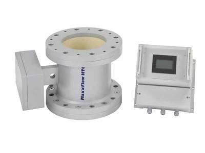
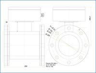
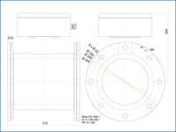
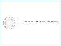
● Small footprint, 220 mm (DN 100), 290 mm (DN 150), 310 mm (DN 200)
● No moving parts, hence no maintenance
What do you want to do?
Use
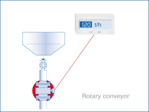
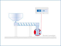
The installation of the MaxxFlow HTC takes place independently of the direction of the line (vertical/inclined), but always after mechanical conveyor elements,
e. g. rotary feeder, screw conveyors, air slides or chain conveyors.
Function
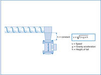
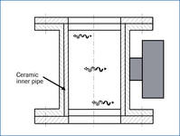
After the conveyor, the material to be measured falls or slides through an inlet path and runs through the sensor. During the throughput, the MaxxFlow HTC records the material type and speed. Since the material falls from a constant height after emerging from the conveyor element, the speed of the product stream is accelerated, but is constant at the installation position of the sensor.
Due to this constant speed, the speed measurement does not need to be activated in every case, but can be calculated as a constant depending on the height of the fall. The mass flow is determined as follows:
Q (kg/s) = K (kg/m3) x v (m/s) x A (m2)
Through the input coupling of a high-frequency, electro-magnetic alternating field, a homogenous measuring field is generated in the measuring tube.
The measuring tube (interior tube of the sensor) consists of wear-resistant Al2O3ceramics. Dry bulk solids inside the measuring field reduce the amplitude of the alternating field.
This leads to a measuring signal that is in proportion to the concentration of the dry bulk solids in the sensor (kg/m3).
If the material speed varies, for example due to a change in initial speed, then this can also be measured.
This takes place through a runtime measurement with the help of two additional electrodes behind the interior ceramics tube.
Mounting and Installation
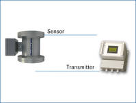
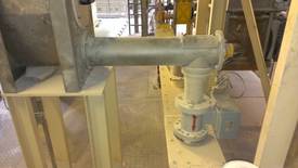
A complete measuring station consists of these components:
• Measuring feeder for installation in the conveyor line
• Transmitter
The measuring feeder is available in sizes DN 100, DN 150 mm and DN 200 mm.
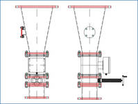
On request the components inlet path (between conveyor element and sensor) and gate valve (for calibration) can also be configured and supplied.
The transmitter is connected to the sensor using 4-wired, shielded cable.
The maximum distance between measuring feeder and transmitter is 300 m.
Technical Data
| Sensor | Housing | Steel St 52, powder-coated (optional stainless steel 1.4571 NW 100/150/200 mm, flange according EN 1092-1 / PN 10 |
|---|---|---|
| Inner pipe | Ceramic AL2O3 | |
| Protection category | IP 65 | |
| Operating temperature | Sensor electronic: 0 … + 60 °C Sensor pipe: – 20 … + 120 °C |
|
| Max. working pressure | 1 bar, optional 10 bar | |
| Working frequency | 88 kHz | |
| Transmitting power | Max. 2 mW | |
| Weight | Depending on model | |
| Accuracy | ± 3 % (based on end of measuring range and calibrated material) | |
| Transmitter (Field housing) | Power supply | 110/240 V AC, 50 Hz, optional 24 V DC |
| Power comsumption | 20 W / 24 VA | |
| Operating temperature | – 10… + 45 °C | |
| Dimensions | 258 x 237 x 174 mm (W x H x D) | |
| Weight | Approx. 2.5 kg | |
| Additional data | RS 485 interface | ModBus |
| Terminal clamp wire size | 0.2 – 2.5 mm_ [AWG 24-14] | |
| Current output signal | 2 x 4 … 20 mA (0 … 20 mA), load < 500 Ohm | |
| Serial output | RS 485, ModBus protocol | |
| Data backup | Flash memory | |
| Cable glands | 3 x M 16 (4.5 – 10 mm Ø) | |
Application Examples
Click on a desired application example to navigate to a detailed description.
Throughput measuring
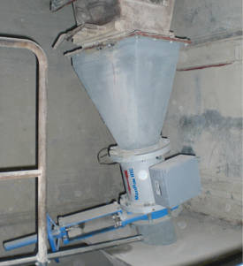
Mass flow measurement
of raw meal
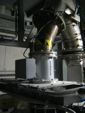
Mass flow measurement of potato starch
in free fall prefeeding chain conveyors
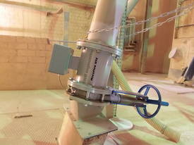
Mass flow measurement of raw meal
in free fall after air slide
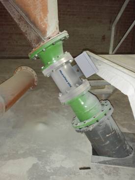
Mass flow measurement of salt
in free fall pre feeding chain conveyor
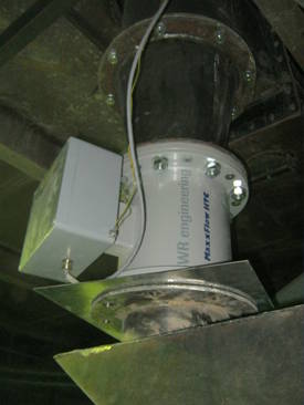
Mass flow measurement
of raw meal after dosing roller
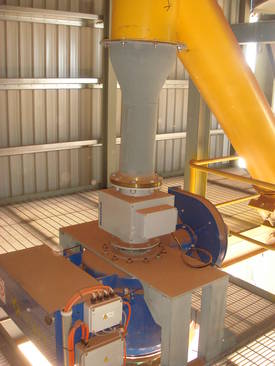
Continuous throughput measuring
of pulverised limestone in pneumatic conveyors
Material admixture
in building material industry
Global Technology Systems
P.O. Box 799 Shalimar, FL 32579. USA
(850) 651-3388
info@onthelevel.com


